
xPowerOS distributed inverting
Four inverters, synchronised in software.
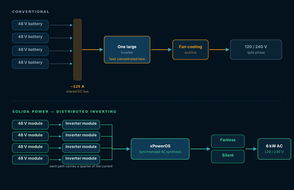
The interesting part of this product is not the battery. It is that each battery module drives its own power-conversion path, and xPowerOS coordinates those paths into one supply — rather than combining four batteries onto a single high-current DC bus and inverting once.
The architecture, stated precisely
48 V DC → distributed AC conversion → line-voltage output
Each 48 V battery independently powers a modular inverter. Solida Power's control software synchronises and coordinates the individual AC outputs, digitally synthesising them into one high-power single-phase supply.
One point of terminology, because it matters. The system does not add 48 V AC to 48 V AC until it reaches line voltage. Electrically, the software is coordinating four modular inverter outputs to synthesise a higher-voltage AC output. The distinction is the difference between a description an engineer will accept and one they will not, and we would rather be precise with you than impressive.
The consequence of that choice runs through everything else on this site: the thermal behaviour, the fanless enclosure, the modularity, the fault handling, and the fact that the phase a unit produces is set in software rather than wired into a transformer.
The chain, end to end
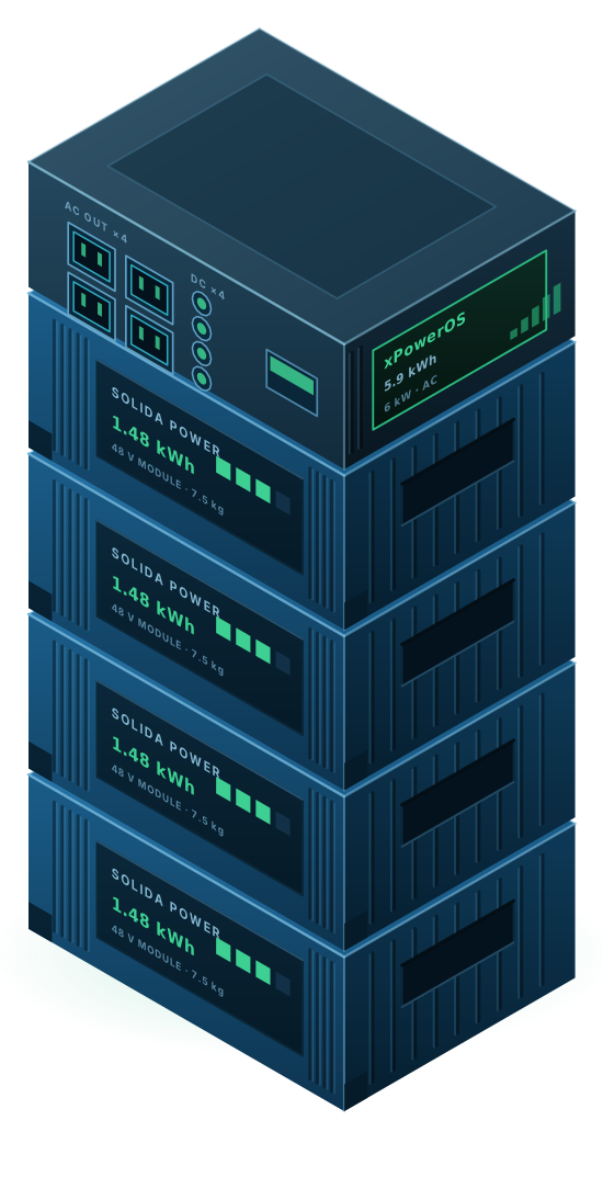
- 4 × 48 V battery module1.48 kWh each, 7.5 kg each
- 4 × inverter moduleone conversion path per battery
- xPowerOS synchronisationcoordinated AC synthesis
- Single-phase AC output6 kW, four outlets
No step in that chain is a shared high-current DC bus. That absence is the design.
Consequence one
No centralised high-current DC bus.
At 6 kW, a conventional 48 V architecture needs roughly 125 A at ideal conditions and realistically more at full load. That current has to travel: through busbars, through contactors, through connectors, all of which have to be sized for it, all of which dissipate heat proportional to the square of it.
Distributing conversion means no single conductor in the system ever carries the full system current. That is not a software feature — it is a straightforward engineering advantage that shows up in mass, in heat, in connector cost and in what can go wrong.
What the shared bus costs you
- Busbars, contactors and connectors sized for the whole system's current
- Resistive loss concentrated at the highest-current points
- A single fault path that the whole system depends on
- Mass and volume that scale with peak current, not with energy
Consequence two
Fanless, passively cooled, silent.
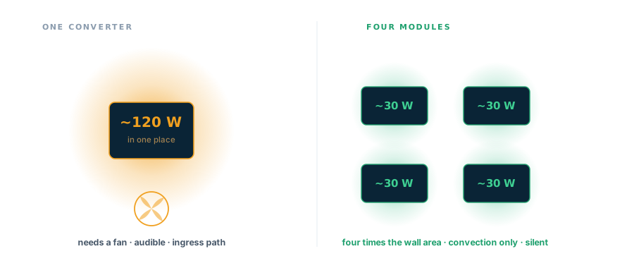
We are careful not to say "no heat," because that would be false. Every real power converter has losses. At 98% efficiency a 6 kW unit still dissipates roughly 120 W; at 99% it is about 60 W. The heat is real.
What the distributed architecture changes is where that heat appears. Instead of 120 W concentrated in one converter — which needs a fan, and therefore an air path, and therefore an ingress route for dust and water — the loss is split across four modules, each with its own enclosure walls to shed it through. Four times the surface area for the same total loss is what makes convection alone sufficient.
- No fan, so nothing audible and nothing to fail
- No forced air path, so no filter to clog and no dust ingress route
- No rotating machinery anywhere in the system
Consequence three
The phase is a setting, not a transformer.
Because the output is synthesised in software, which phase a unit produces is a control parameter. That is what the three-position knob on the front panel selects. It does not make one unit three-phase — a single machine still puts out one phase — but it means three units can be set to phase 1, phase 2 and phase 3 and joined by the combining connector without a different product, a different firmware load or a transformer between them.
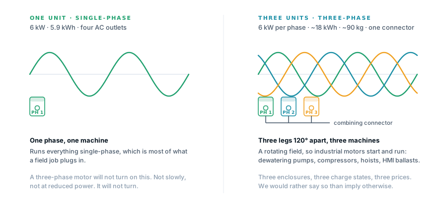
Three-phase takes three units. One unit is a single-phase machine — 6 kW, 5.9 kWh, four AC outlets. Its front panel carries a phase selector, so three units set to phase 1, phase 2 and phase 3 and joined by the combining connector will feed a three-phase load at 6 kW a phase. That is three enclosures, three charge states and roughly 90 kg for about 18 kWh. We say so plainly because an earlier version of this site claimed three-phase came out of a single box, and it does not. The three-unit specification →
Fault isolation between modules
Conversion paths are independent, so the failure of one battery-and-inverter branch is contained rather than systemic. In a field clinic holding a cold chain, or a storm response running a dewatering pump, that difference is the product.
Software-defined output
Output voltage, phase assignment and behaviour under load are determined by xPowerOS rather than by fixed magnetics. The same hardware serves 120 V and 230 V, and any of the three phase positions, without a different product.
What we do not claim
Where the honest limits are.
Three things we could overstate on this page and have chosen not to.
We did not invent distributed conversion
instagrid has shipped distributed per-module power electronics with passive cooling for around six years and is well funded. Claiming architectural novelty would invite an easy rebuttal and cost us credibility in exactly the technical rooms we need to be believed in. The claim we make is about integration: this much energy and this much continuous power, fanless, in an enclosure whose heaviest single part is 7.5 kg.
We have not published surge figures
Induction motors draw six to eight times running current at locked rotor, and surge headroom — not continuous rating — is what determines whether a pump actually starts. We are measuring locked-rotor starting into representative motor loads and will publish the number as measured. If you are specifying this for motor-driven work, ask us for the current data before you commit.
This is off-grid only
It has no grid-interactive function and is not intended for utility interconnection. We state that plainly to certification bodies and let them make the formal standards determination for our topology and intended use, rather than asserting which standards apply to a distributed inverter topology.
On the numbers. Figures on this site are engineering targets for the pre-production unit, not measurements from a certified production sample. Peak and 10-second overload ratings are under test and will be published as measured, because surge headroom — not continuous rating — is what decides whether a motor actually starts. Competitor specifications are vendor-published figures gathered in August 2026. If you are evaluating this for a purchase decision, ask us for the current test data rather than relying on this page.
Talk to us
Want the engineering detail?
Deeper architecture, synchronisation behaviour, fault handling and test data are available under NDA. Tell us what you are evaluating and we will get the right engineer on the call.