
Specifications
Everything we can state today.
Including the numbers that are still under test, marked as such. A specification sheet that hides its open items is not a specification sheet — so the six things we have not settled get their own section at the bottom of this page.
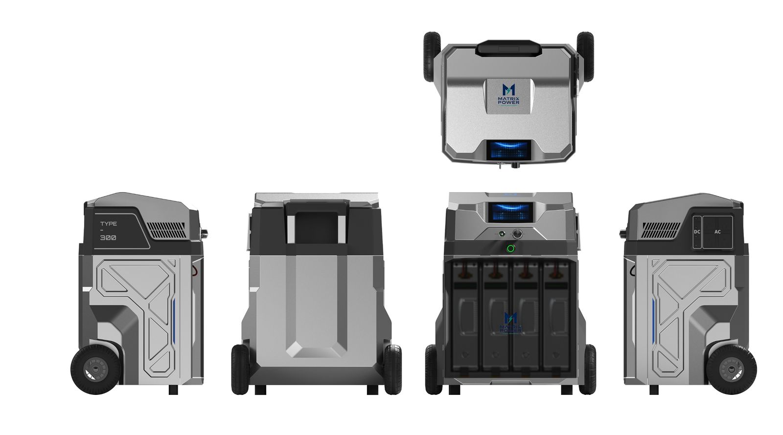
Energy & modules
- Usable energy, 4-module system
- 5.9 kWh
- Energy per battery module
- 1.48 kWh
- Module nominal voltage
- 48 V DC
- Modules per system
- 4 (expandable)
- Mass per battery module
- 7.5 kg
- System mass, 4 modules + head
- ~30 kg
Output
- Continuous output
- 6 kW
- Output topology
- Single-phase AC, one unit
- Line voltage
- 120 / 230 V, configured at order
- AC outlets
- 4
- DC outputs
- 4
- Phase selector
- Phase 1 / 2 / 3, on the front panel
- Waveform
- Pure sine, software-defined
- Peak / 10-second overload
- Under test — published on measurement
Three-phase, as a three-unit set
- Units required
- 3, plus the combining connector
- How it is configured
- Each unit set to phase 1, 2 or 3 at its front panel
- Output
- 6 kW per phase
- Combined usable energy
- ~18 kWh (3 × 5.9 kWh)
- Combined mass
- ~90 kg across three enclosures
- Line-to-line voltage
- 208 V or 400 V, per unit configuration
- A single unit alone
- Cannot produce three-phase output
Enclosure & handling
- Dimensions (L × W × H)
- 444 × 370 × 600 mm
- Wheels
- Two 6-inch directional wheels
- Handle
- Retractable tow handle, stowed flush
- Ground clearance while towed
- 54 mm at 45° tilt
- Module access
- Translucent front door, press-latch with damped return
- Module retention
- Sliding lock; the module withdraws downward, by its own handle
- Output bay
- Flip-up cover over the AC and DC ports
Materials & finish
- Top cover
- Moulded plastic, painted, fine matte, part screen-printed
- Top cover colour
- PANTONE Cool Gray 9C, pearl metallic
- Front door and port cover
- Translucent PC, fine matte, screen-printed mark
- Lower body
- Moulded plastic, natural-colour injection, fine matte
- Lower body colour
- PANTONE Cool Gray 11C
- Colourways
- Liquid silver, navy blue, natural grey, desert tan
Thermal & acoustic
- Cooling
- Passive convection, fanless
- Moving parts
- None
- Acoustic output
- No fan, no rotating machinery
- Dissipation at full load
- Distributed across four module walls
Platform
- Control software
- xPowerOS
- Display
- Colour panel on the top face
- Architecture
- Distributed per-module inversion, synchronised AC synthesis
- DC bus
- None — no centralised high-current 48 V bus
- Fault behaviour
- Per-module isolation
- Telemetry
- Per-module state of charge, delivered kWh, duty cycle
Grid & certification
- Grid interaction
- None — standalone off-grid only
- Transport classification
- Class 9, UN3480 / UN3481
- Certification
- In progress — see the note below
Three-phase takes three units. One unit is a single-phase machine — 6 kW, 5.9 kWh, four AC outlets. Its front panel carries a phase selector, so three units set to phase 1, phase 2 and phase 3 and joined by the combining connector will feed a three-phase load at 6 kW a phase. That is three enclosures, three charge states and roughly 90 kg for about 18 kWh. We say so plainly because an earlier version of this site claimed three-phase came out of a single box, and it does not. The three-unit specification →
Open items
What we have not settled, and why we are telling you.
Four questions a serious buyer will ask that we cannot yet answer with a measured number. Here is where each one stands.
Peak and 10-second overload rating
Induction motors draw six to eight times running current at locked rotor. Surge headroom, not continuous rating, is what determines whether a pump, compressor or hoist actually starts. We are measuring locked-rotor starting into representative motor loads and will publish the figure as measured. If your application is motor-driven, this is the number to ask us for.
The combining connector
Three-phase output requires three units, each set to a different phase, joined by a combining connector. The units are specified; the connector is not finished. Its rating, its earthing and neutral arrangement, and what happens when one of the three units drops out mid-load are open engineering questions, and they are the ones a fleet engineer will ask first. We will publish the answers before we sell the configuration, not after.
Transport classification
A 5.9 kWh pack is Class 9 dangerous goods under UN3480/3481, and cells above 100 Wh face heavy air-freight restriction. The modular architecture is the answer here — shippable at reduced state of charge, in DG-certified cases — but we are documenting that compliance path before we market rapid air deployment as a capability.
Certification scope
We expect UL 2743 for the portable pack, UN38.3 for transport, FCC Part 15 for emissions, an IP rating for field use, and MIL-STD-810/461 if defense work proceeds. We tell the NRTL plainly that this is a standalone off-grid inverter with no grid-interactive function and no intended utility interconnection, and we let them make the formal standards determination. We expect them to scrutinise fault behaviour and isolation between modules, because a distributed inverter topology is not what a standard test plan assumes — and to look hard at the three-unit configuration separately from the single unit.
On the numbers. Figures on this site are engineering targets for the pre-production unit, not measurements from a certified production sample. Peak and 10-second overload ratings are under test and will be published as measured, because surge headroom — not continuous rating — is what decides whether a motor actually starts. Competitor specifications are vendor-published figures gathered in August 2026. If you are evaluating this for a purchase decision, ask us for the current test data rather than relying on this page.
Talk to us
Need a figure that is not on this page?
Ask. If we have measured it we will send it, and if we have not we will tell you when we expect to.